Lab series# 13: Mass Spectrometry Instrumentation Principles
Greetings,
In an earlier post, I had talked about a method called MALDI-TOF (A method in Mass spectrometry) which is making its way into the Microbial diagnostics. The post was more concentrated on my experience with the technique and how it aids microbial identification. Though I talked a little bit about the basics of Mass Spectrometry it was not elaborate. In this post, let us explore Mass Spectrometry instrumentation in detail
 |
| Table 1: Common applications of MS. Source |
Mass Spectrometry (MS) is an analytical technique, for analysis of chemicals through ionisation and sorting via mass to charge ratio. Every individual chemical is different. Every chemical has a combination of mass and charge ratio that is absolutely unique to it.
These days when you say the word "Mass spec", it largely indicates Proteomics. But that is not true. Any chemical that can be charged and has got a mass can be analysed on a mass spec. Table 1, shows a list of applications that MS can achieve.
MS is actually a method to calculate mass to charge ratios (m/z) and relative abundances for any given molecule. In this case, m stands for mass and z stand for charge number of ions. The number of electrons removed is known as the charge number. m/z represents mass divided by charge number and the horizontal axis in a mass spectrum is expressed in units of m/z. Consider you have two types of balls one heavier and the other lighter. Assume that the balls are travelling at a speed and you have a strong air flowing in a perpendicular path. The lighter is the ball, easier is it to deflect its path. In essence, if you know the original path, speed and the force used for deflection, you can calculate the mass of the ball. Now scale the whole process to an atomic level in a vacuum (10-6 to 10-8 torr) to avoid a molecular collision. That's pretty much how a classic MS works.
 |
| Fig 1: Construct of a Mass Spectrometer. Source |
Stage 1: Ionisation
The atom is ionised by knocking one or more electrons off to give a positive ion. This principle is true for all chemicals including inert materials. Knocking off an electron effectively removes 1 unit of negative charge and hence the molecule is effectively rendered positive charge. Mass spectrometers always work with positive ions. In a majority of case, molecule holds a charge of +1, since it is very difficult to knock off the second electron from an already positively charged molecule.
Stage 2: Acceleration
The ions are accelerated so that they all have the same kinetic energy. This step gives equal chance to all the molecules to fly into the detector and hence their arrival in the detector is now based solely on their mass-charge ratio.
Stage 3: Deflection
The ions are deflected by a magnetic field according to their masses. The degree of deflection depends on the amount of positive charge the molecule is holding and the mass (As already explained).
Stage 4: Detection
The beam of ions passing through the machine is detected electrically, converted to a digital signal and independently analysed by a software and presented in the form of a data.
From the perspective of functional process, Modern MS operates at 3 functional levels, handled by 3 different components.
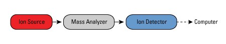 |
| Fig 2: Basic components of MS. Source |
- Ion source- Responsible for Ionisation of the molecule
- Mass Analyser- Responsible for separation of ions based on their mass-to-charge ratio
- Ion detector- Takes care of detecting and amplifying the signal
The combination of Ion source and Mass analyser determines what type of MS we are talking about. For example- MALDI-TOF is a system where MALDI is the Ionisation source and TOF is the Mass analyser.
Methods in Ionisation:
 |
| Table 2: Details of a variety of Ionisation process used for MS. |
Ionisation is the process of removing an electron from the molecule rendering it positively charged. The actual technique of ionisation to be employed depends on what is to be ionised. For example, biological specimens and proteins are preferentially ionised by MALDI or ESI. The method of ionisation can be classified into 2 types- Hard and Soft. Hard ionisation techniques are processes which impart high quantities of residual energy in the subject molecule thereby involves large degrees of fragmentation of the molecule. In contrast, soft ionisation imparts little residual energy onto the molecule and therefore result in lower fragmentation. Each method has its own applicability, advantages and disadvantages. See Table 2 for summarised details of most common methods.
Types of Mass Analysers (MA):
Electron Multipliers are useful when the Ion current detected is in the range less than 10-15 amp. When a primary ion strikes a suitable surface (such as that made from CsSb, GaP or BeO) secondary electrons are released. These electrons further stimulate next set of electrons leading to essential amplification. An electrode which emits additional electrons in a photomultiplier or similar amplifying device is called as Dynode. There are 2 subtypes of this design
A Faraday cup (Also known as cylinder electrode detector) is a metal (conductive) cup designed to catch charged particles in vacuum. The resulting current can be measured and used to determine the number of ions or electrons hitting the cup. The Faraday cup is a relatively insensitive detector in comparison to Electron multipliers but is very robust. It is ideally suited for isotope analysis where the signal is higher.
All types of MA are based on strong electromagnetic forces applied on the charged Ions. The separation is guided by Lorentz force law and Newton's second law. The acceleration is mass- dependent and dependent on the ionic charge. Therefore, separation of ions will be based on to their m/z value rather than by their mass alone. However, as already discussed in a majority of cases the z=1 and hence separation is based on mass.
Mass analysers are basically divisible into 2 different types- (i) Scanning Ion Monitoring (ii) Selected Ion Monitoring. In scanning ion versions (Ex: TOF) all Ions are studied and analysed whereas in selected ion version (Ex: Magnetic sector and quadrupole mass spectrometers) data is collected only for the masses of interest for specific compounds thereby improving sensitivity. See Table 3, for details of some of the most commonly used Mass analysers.
 |
| Table 3: Features of most commonly used Mass analysers |
Amongst all of the above, Trapped- Ion MA (More commonly known as Ion traps) are the best and merits some additional discussion. An Ion trap is defined as "Combination of electric or magnetic fields used to capture charged particles, in a system isolated from an external environment." Based on the physics behind the methodology there are different types of traps- Penning trap, Paul trap and Kingdon trap.
The most talked about technology- The Orbitrap is a type of Kingdon trap. Kingdon trap was developed by KH Kingdon. The system consists of a cylindrical outer electrode and a thin wire centre electrode.
 |
| Fig 3: Orbitrap analyser. Source |
An orbitrap consists of an outer barrel-like electrode and a coaxial inner spindle-like electrode that traps ions in an orbital motion around the spindle. The ions are trapped in an electrostatic field, with central electrode kept at a high voltage. The image current from the trapped ions is detected and converted to a mass spectrum using the Fourier transformation of the frequency signal.
However, injecting the Ions to the trap in itself poses with certain challenges. The problems are overcome by using a separate injection device called as C-trap (curved linear trap for ion injection). The C-trap basically packets the Ions together and injects it into the Orbitrap in batches. Each packet contains a multitude of ions of different velocities spread over a certain volume, therefore, ions will move with different rotational frequencies but with the same axial frequencies. Figure 3 shows a Cross section of the C-trap ion accumulation device and the Orbitrap mass analyser with an example of an ion trajectory. During the voltage ramp, the ion packets enter the Orbitrap mass analyser forming rings that induce current which is detected by the amplifier.
However, injecting the Ions to the trap in itself poses with certain challenges. The problems are overcome by using a separate injection device called as C-trap (curved linear trap for ion injection). The C-trap basically packets the Ions together and injects it into the Orbitrap in batches. Each packet contains a multitude of ions of different velocities spread over a certain volume, therefore, ions will move with different rotational frequencies but with the same axial frequencies. Figure 3 shows a Cross section of the C-trap ion accumulation device and the Orbitrap mass analyser with an example of an ion trajectory. During the voltage ramp, the ion packets enter the Orbitrap mass analyser forming rings that induce current which is detected by the amplifier.
Ion Detectors
Once the molecules are spatially separated based on the m/z ratio, the molecule strikes on the detector. The Ions are electrically detected but usually the signal is extremely weak to make a meaningful data. The function of the detector thus is also to amplify the signal. An ideal detector would have very high amplification, rapid response and a very low noise. There are several types of detector available in the market. By far, 3 types of detector have been used commonly- Electron multipliers, Faraday Cups and Microchannel plates.
 |
Fig 4: Schematics of the two main types
of electron multiplier. Source
|
- Discrete dynode electron multiplier
- Continous dynode electron multiplier
 |
| Fig 5: A schematic diagram of a Faraday cup ion detector. Source |
 |
| Fig 6: Illustration of microchannel plate. Source |
Tandem MS or MS/MS
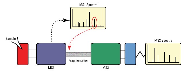 |
| Fig 7: Illustration of Tandem MS. Source |
Mass spectrometry is inherently designed to detect and analyse multiple sets of molecules in a rapid time. However, complex samples (most biological samples) are difficult to be analysed with high depth. This problem can be overcome by using an approach called as Tandem MS. Tandem MS represents 2 MS integrated together to perform a very detailed analysis. For example in Tandem MS for protein analysis, peptide ions are formed in the ion source and separated by m/z ratio in the first stage of mass spectrometry. The data is represented as MS1. The peptide Ions breaks into component amino acids through collision-induced dissociation (or other methods) which is separated and detected in the second stage of MS (Data available as MS2). An example schematic of Tandem MS is shown in Fig 7.
Sample injection System for Mass Spectrometry analysis:
When dealing with the analysis of a complex mixture of analytes, introducing all the analytes at once is a problematic situation. There is an inherent limit to how much data can be acquired in a given time for any MS run. For a complex sample, there are too many ions to be detected and analysed. Of course, use of tandem design reduces the problem but there had still been too much complexity. Thus, instead of introducing the whole sample, analytes can be introduced part by part. Let me try an example. Let's say you are analysing a tissue containing about 4000 proteins. There are some abundant proteins which forms a major chunk of protein percentage. Since they are too many in number introducing everything in a single time, the data will capture mostly the major ones. If we spatially separate the sample in such a way that we inject say about 10-20 proteins at a time all of them will be detected. The exact number depends on a variety of factors based on machine design.
Though sample injection is not actually a part of MS, its working is so important that sample injection is considered as a part of MS design. Most modern MS is integrated with HPLC. HPLC-MS/MS (These days they are more commonly known as LC-MS/MS) combines the physical separation capabilities of liquid chromatography with the tandem mass analysis capabilities of MS. In proteomics, chromatographic separation beforehand gives an edge in an analysis. For example, Isomers of a molecule have the same mass and thus multiple isomers may give same MS readout. With HPLC these can be separated before introducing it into MS thus sufficiently differentiating the types. Another idea is to get over the problem of a phenomenon called as "Ion suppression". When a poorly ionised analyte is present in a mixture containing a large amount of something else (such as a buffer), the analysis is significantly affected. Chromatography can largely overcome this issue though cannot be absolutely eliminated.
To summarise working of an MS in a single line, protein preparation is separated using methods such as HPLC which is fed into the Ion source, Ionise, separate the molecules based on m/z value and be detected using detector.
I have tried to limit myself to talking about the basics of MS working without getting into the physics of it. I have also tried to avoid extreme details of working and hence have purposefully omitted several things in the post. In a future post, I will come back with details of how MS is used for proteomics.
Julia H. Jungmann, & Ron M. A. Heeren (2013). Emerging Technologies in Mass Spectrometry Imaging Journal of Proteomics, 75, 16, 5077-5092, 2012 arXiv: 1305.5433v1


Comments
Post a Comment